A good VSWR reading tells you that the antenna port is well matched to the feed line. That is useful, but it is only part of the picture. VSWR does not show whether the antenna actually sends energy in the right direction, at the right strength, across the coverage area you need. To answer those questions, you need radiation measurements taken in a controlled environment. That is where our microwave anechoic chamber comes in.
What Is a Microwave Anechoic Chamber?
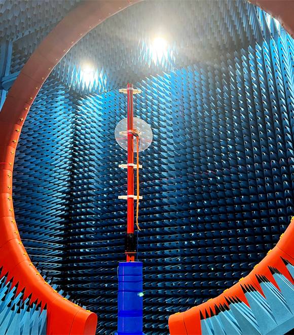
A microwave anechoic chamber is a shielded room whose walls, floor, and ceiling are lined with RF-absorbing material. The absorbers reduce reflections from the room surfaces, and the shielding blocks external RF interference. Together, these features create a controlled measurement environment that approximates free-space conditions.
Inside the chamber, the antenna under test (AUT) is mounted on a positioning fixture. A reference antenna at the opposite end transmits or receives a known signal. By rotating the AUT and recording the received power at each angle, the system produces a radiation pattern and a gain measurement that would be difficult to obtain reliably in an open environment with reflections, multipath, and nearby interference sources.
How BBT ANTENNAS Tests Antennas
Our antenna test process follows three stages. The goal at each stage is to compare real measurements against the RF requirements that both sides agreed on at the start of the project.
- Review the agreed RF and mechanical requirements. Before any measurement, we confirm the target frequency bands, gain, radiation pattern shape, VSWR limit, connector type, and mechanical constraints with the buyer. These agreed targets become the pass/fail reference for the test.
- Check VSWR / S11 with a VNA, then measure gain and radiation pattern in the chamber. VSWR and return loss are checked using a vector network analyzer (VNA), which tells us how well the antenna port matches the feed line across the operating band. Gain and radiation pattern are then measured inside the microwave anechoic chamber. AUT mounting position, orientation, and fixture setup all affect the results, so we set them to match the intended installation condition as closely as practical.
- Compare the sample with the agreed targets and review whether adjustment is needed. We compare the measured VSWR, gain, and pattern data against the requirements from stage one. If a parameter falls outside the target, the engineering team reviews whether an antenna design adjustment, a fixture change, or a re-test is needed before the project moves to the next phase.
What the Test Results Tell an OEM or ODM Buyer
Each measurement answers a different question about antenna performance. The table below summarizes the three measurements BBT ANTENNAS provides and why each one matters for a project decision.
| Measurement | What it shows | Why it matters |
|---|---|---|
| VSWR / return loss | How well the antenna port matches the feed line across the operating band. A lower VSWR means less signal is reflected back. | Poor port matching wastes transmit power and can degrade receiver sensitivity. VSWR is a port-level indicator and does not describe how the antenna radiates. |
| Gain | How much signal strength the antenna adds (or loses) in its peak direction compared to a reference. | Gain determines whether the antenna can deliver the link budget your system needs at the required distance. Measured in the chamber to remove environmental interference. |
| Radiation pattern | How the antenna distributes radiated energy in space, usually shown as a polar or rectangular plot across azimuth and elevation angles. | The pattern shows whether coverage matches your installation scenario: wide for omni applications, narrow for point-to-point links, or shaped for sector coverage. |
VSWR confirms that the signal enters the antenna efficiently. Gain and radiation pattern confirm that the signal leaves the antenna in the right direction and at the right strength. A complete evaluation needs both sides of that picture.
Why VSWR Alone Is Not Enough
VSWR answers one question: how much of the input signal gets into the antenna versus how much gets reflected back. It is a port-matching measurement. It does not tell you where the energy goes after it enters the antenna, or how much of it reaches the intended coverage area.
An antenna can show a VSWR below 1.5:1 across the operating band and still deliver low gain or a pattern that points in the wrong direction. The energy might be absorbed in losses, radiated in an unwanted direction, or spread too widely to be useful. Without a gain measurement and a radiation pattern from a controlled chamber environment, a passing VSWR result can give false confidence in a design that does not actually perform.
That is why our antenna test system includes both port-level checks (VSWR/S11 on the VNA) and radiation measurements (gain and pattern in the anechoic chamber). Together, they give a more complete picture of whether the antenna meets the project requirements.
How Test Data Supports Custom Antenna Development
For OEM, ODM, and custom antenna projects, chamber test data plays a specific role at the sample evaluation stage.
- Requirement confirmation. Before testing, both sides agree on the RF targets: bands, gain, pattern shape, VSWR limit. The test data is then compared directly against these targets.
- Sample comparison. If a prototype sample falls short on gain or shows an unexpected pattern shape, the data helps the engineering team identify where the design needs adjustment. Rather than guessing, the team can work from measured evidence.
- Design review before production. Adjusting an antenna design at the prototype stage is far less expensive than discovering a performance problem after volume production. Chamber testing provides a checkpoint between sample approval and mass production.
Not every project follows an identical testing sequence. The scope of testing depends on what was agreed for each project. For a closer look at how BBT ANTENNAS handles custom antenna projects from requirement to delivery, see our custom antenna design and OEM/ODM services page. For factory, quality, and production details, see our antenna manufacturing capabilities.
What to Send for an Antenna Test or Custom Project
If you are preparing to discuss an antenna test, custom design, or OEM/ODM project, having the following details ready will help us give you a clear and specific response:
- ▪ Operating bands (frequency range or specific channels)
- ▪ Target gain (dBi, with direction if applicable)
- ▪ Required coverage or radiation pattern (omni, sector, directional, or a specific beamwidth)
- ▪ Antenna dimensions (size constraints or form factor)
- ▪ Connector and cable (type, length, and position)
- ▪ Mounting condition (pole, wall, ceiling, PCB, or enclosure)
- ▪ Installation environment (indoor, outdoor, vehicle, industrial, marine)
- ▪ Expected quantity (sample, pilot run, or production volume)
The more complete your input, the faster we can confirm whether an existing design fits or a new design is needed, and what testing will be included.
Frequently Asked Questions
What is a microwave anechoic chamber used for?
A microwave anechoic chamber is a shielded room lined with RF-absorbing material. It reduces reflections and blocks outside interference so that antenna measurements such as gain and radiation pattern can be taken in a controlled environment that approximates free-space conditions.
What antenna measurements can BBT ANTENNAS provide?
BBT ANTENNAS measures VSWR and return loss with a vector network analyzer, and measures gain and radiation pattern in the company's in-house microwave anechoic chamber. These three measurements cover port matching, signal strength in the intended direction, and how energy distributes around the antenna.
Is anechoic chamber testing the same as EMI/EMC compliance testing?
No. Antenna testing in an anechoic chamber focuses on intended RF performance: gain, radiation pattern, and port matching. EMI/EMC compliance testing focuses on unintended emissions and immunity to external interference. The two serve different purposes and follow different procedures.
Why is VSWR testing not enough on its own?
VSWR shows how well the antenna port matches the feed line, but it does not reveal how the antenna radiates energy into space. An antenna can show good VSWR while delivering low gain or an unusable radiation pattern. Chamber-based radiation measurements fill that gap.
How does chamber testing support an OEM or ODM antenna project?
Chamber testing lets the engineering team compare a prototype sample against the agreed RF targets before production. If gain, pattern, or VSWR falls outside the requirement, the design can be adjusted and re-tested. This verification step reduces the risk of discovering performance problems after volume production has started.
Discuss Your Antenna Test Requirements
Send us your operating bands, target gain, radiation pattern or coverage requirements, antenna dimensions, connector, mounting environment, and expected quantity. We will confirm the testing scope and next steps for your project.
Send Your Antenna Requirements